Risk assessment and risk reduction

ISO 12100:2012 – Safety of machinery – General principles for design –
Risk assessment and risk reduction

As a result of their functionality, machines and plants represent potential risks for the workers. If a machine may present hazards, a risk assessment is required and, if relevant, a risk reduction shall be undertaken to reduce the risk to an acceptable level.

ISO 12100 provides a methodology for the design of machines that shall be safe for their intended use. It gives provisions:

  • For identification of the hazards
  • For estimation and evaluation of the risks associated with the machine
  • On how to remove hazards or provide sufficient risk reduction

ISO 12100 is a type-A standard.

For USA equivalent information is given in ANSI 12100.

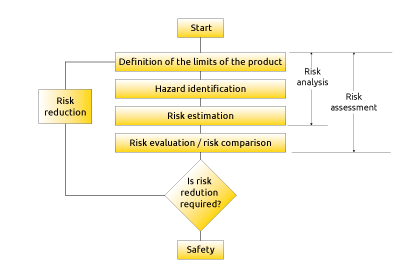
Strategy for risk assessment and risk reduction

Risk assessment is comprehensive method to enable in a systematic way the analysis and evaluation of risks. It must be carried out during the design, construction and commissioning of the machinery and every time are made modifications. It can also be used for the evaluation of existing machinery if, for example, there have been accidents or malfunctions.

To implement risk assessment and risk reduction the following actions shall be taken

  1. Risk analysis
    to determine the limits of the machinery, which include the intended use and any reasonably foreseeable misuse, and to identify the hazards and associated hazardous situations associated to the person’s activities (all safeguards should be ignored while hazard identification is performed).
  2. Risk evaluation
    To evaluate the risk for each identified hazard and hazardous situation and take decisions about whether there is a need to reduce risk.
  3. Risk reduction
    If the hazard cannot be removed, reduce the associated risk by implementing protective measures.

The process is iterative, and several successive applications can be necessary.

Fig. 1 – Strategy for risk assessment and risk reduction

The goal to be met is to reduce risk to an acceptable (tolerable) level considering that the risk reduction achieved: should be effective throughout all phases the machine life cycle and should not impair machinery functions and usability.

When changes are made to the process or to the machine or if protective measures are added, all steps of the risk assessment should be repeated to check whether:

  • There have been changes to the operating limits of the machine
  • New hazards or dangerous situations have been introduced
  • The level of risks of any existing dangerous situations has been increased
  • Protective measures added are effective in reducing the risk
  • The risk reduction intended has been achieved

Achieving the required risk reduction is only one of the inputs to the decision to stop the iterative risk reduction process. This decision should involve additional considerations such as regulations, national laws, and work organization.

Determination of the limit of the machine

The first step of the risk analysis consist in providing a clear description of the mechanical, physical and functional capabilities of the machinery; to determine the space limits of the machinery which means to determine the range of movements, the space requirements for persons interacting with the machine (also during maintenance) the kind of human interaction, the environmental operating limits (minimum and maximum temperatures, dry or wet weather, tolerance to dust etc.), different operating modes, power supply interface.
 

Identification of the hazards

After determination of the limits of the machinery, the essential step in any machinery risk assessment is the systematic identification of reasonably foreseeable hazards that may arise during the whole machine life cycle (transport, Installation, commissioning, use, disabling, dismantling). Only if all the hazards are correctly identified action can be taken to reduce the associated risks. Unidentified hazards can lead to injury. It is therefore important to ensure that the identification of hazards is systematic and complete.
 
To accomplish the hazard identification, it is necessary to identify:
 
  • The operations to be performed by the machinery 
  • The tasks to be performed by persons who interact with the machine, considering unintended behavior or reasonably foreseeable misuse of the machine 
  • The characteristics of the materials to be processed 
  • The environment in which the machine can be used
Hazards generated by man-machine interactionHazards generated by the machine
SettingElectrical hazards
TestingMechanical hazards
ProgrammingThermal hazards
Manual loading-unloadingHazards generated by noise
Tool changeoverHazards generated by vibrations
Starting, stopping the machineHazards generated by radiation
Restart after unscheduled stopHazards generated by materials
Cleaning and housekeepingHazards related to the environment
Preventive and corrective maintenanceHazards related to emission of substances


Once the hazards and hazardous situations have been identified, an estimate of the risks associated with each hazard and each hazardous situation must be carry out. Converting the impact of risk into numerical terms is a difficult task because there is no universal scale of risk. ISO 12100 has decided to define the risk as a combination of the severity of harm and the probability of occurrence of that harm.

Risk can thus be measured by creating a scale based on the product of consequence (in terms of injury to persons) and probability of occurrence (likelihood of an event causing injury).

Risk = Consequence of harm x probability of occurrence

Typically, to improve the accuracy of the estimate of the probability of occurrence of harm, additional parameters are added such as the frequency and duration of exposure to the hazard, the probability of occurrence of a hazardous event and the technical and human possibilities to avoid or limit the harm.

The formula then becomes:

Risk = Consequence of harm x (time of exposure + probability of occurrence + possibility of avoiding the risk or limiting the harm)

A variety of tools have been developed to assist with this process, these include tables, risk graphs, numeric methods.

Example of Risk graph

S: severity of injury
S1: reversible
S2: irreversible or died

F: frequency or time exposure to hazard
F1: rare / short
F2: continuous prolonged

O: probability of occurrence of the hazard
O1: very low
O2: low
O3: high

A: avoidable risk or limitation of damage
A1: possible
A2: impossible

Example of risk matrix
ConsequencesSeverityClass Cl (Fr+P+Av)   
G3-45-78-1011-1314-15   
Dead, losing an eye or arm4       Unaccettable risk
Permament injury: losing a finger3       Moderate risk
Reversible injury, medical attention2       Tolerable risk
Reversible injury, first aid1        
 
Frequency of exposure, Fr Probability of occurrence, P Probabilities of avoiding or limiting harm, Av
≥ 1 per hour5 Very high5 Impossible5
< 1 per hour
≥ 1 per day
5 Probable4 Possible3
< 1 per day
≥ 1 per 2 week
4 Possible3 Probable1
< 1 per 2 week
≥ 1 per 1 year
3 Low2   
< 1 per year2 Very low1   
 
Fig. 2 – Example of risk matrix
 
The choice of the method to be used for risk estimation is largely linked to the type of machinery and the nature of the hazards. It is also necessary to take into account the skills, experience and preferences of the team making the
assessment.
 
Compliance with the rules for the estimation of the risk is more important than trying to achieve absolute accuracy of the results.

After risk evaluation has been completed, an analysis shall be carried out to determine if any dangerous situations require further risk reduction. Implementing risk reduction means to reduce risk to persons to an “acceptable” level of residual risk.

Safety does not mean zero risk
 
Zero risk only possible when the hazard is FULLY removed
 
Safety means freedom from unacceptable risk

In general, there is industry agreement that a risk reduction strategy should utilize a hierarchical approach referred to as the three-step method.
The three-step method shall be applied in the following sequence:

Step 1 - integration of safety concepts at the design stage
Inherently safe design is the first and most important step in the risk reduction process because protective measures which are integral to the machine design are likely to remain effective, while experience has shown that even well-
designed safeguarding can fail or can be violated or information for use may not be followed. Inherently safe design measures are achieved: 
  1. By a suitable choice of mechanical design features for example, by avoiding sharp edges, corners, and protruding parts, by avoiding crushing points, shearing points, and entanglement points
  2. By designing machines to have sufficient stability in their specified conditions of use.
    Factors to be considered include
    – The geometry of the base and the weight distribution, including loading 
    – The dynamic forces due to movements of parts of the machine or of elements held by the machine which can result in an overturning moment
    – vibration, oscillations 
  3. By reducing the interaction between the exposed persons and the machine. This objective can be achieved by limiting the time to exposure to the hazard, for example, by means of:
    – Automatic loading and unloading stations
    – Setup and maintenance work from outside the hazardous zones
    – Use of reliable components to reduce maintenance work
    – Clear and unambiguous operating concept (e.g., precise marking of controls)
    – Use of Lock-Out/Tag-Out procedure
  4. By limiting the exposure to electrical power (direct and indirect contact) A stable power supply is particularly important in safety-related applications. Voltage supplies must withstand brief power failures. A power supply isolation device must be provided for every power supply connection. For 24 V DC power supplies, use Class 2 circuit which offers protection for fire initiation and electric shock. Another option to provide protection against electric shock is to use safety extra-low voltage (SELV, PELV).
  5. By using suitable enclosures for protections for electric components. Electrical equipment enclosures must meet the requirement for enclosure ratings. Two widely accepted rating systems are the NEMA types/number and the IP rating code.
    The enclosure ratings describe the protection against the ingress of water and foreign objects (dust). In addition, they describe protection against direct contact with live parts.
    NEMA (National Electric Manufacturers’ Association) is commonly specified at installations in the U.S. IP (International Protection), is derived from the IEC and is typically used in Europe.
    Typically, control cabinets should be NEMA 13 or IP 54.
  6. By selecting components that are immune to the disturbances to be expected. The machine and the components used shall be selected so that they are immune to the expected electromagnetic disturbances. Increased requirements apply to safety components.
    The following design guidelines will help to prevent EMC problems:
    – Continuous equipotential bonding by means of conductive connections between parts of machinery and systems
    – Physical separation from the supply unit (power supply/ actuator systems/inverters)
    – Screen shall not be used to carry equipotential bonding currents
    – Connect any grounding/functional earth (FE) provided
    – Use of twisted cables to transmit data (fieldbus)
  7. By preventing unexpected start-up. The connection to mains electricity supply or switching-on of an external power supply shall not result in the starting of working parts of a machine.

    A spontaneous restart of a machine after power interruption shall be prevented (for example, by use of a self-maintained relay, contactor, or valve).

    Every machine shall be equipped with a control for stopping the machine in normal operation.

A command to stop the machine shall have a higher priority than the commands for putting the machine into operation.
 
A Category 0 stop function shall be available as a minimum.
 
  • Stop Category 0: uncontrolled stop by immediately removing power to the machine actuators (drive elements)
  • Stop Category 1: controlled stop with power available to the machine actuators to achieve the stop, then power is removed when the stop is achieved 
  • Stop Category 2: controlled stop with power left available to the machine actuator
Step 2 - Add protective measures against risks that cannot be removed by design

Step 2 – Risk reduction by means of protective measures

If the hazards cannot be removed or the risks cannot be adequately reduced by inherently safe design measures, additional protective measures must be applied, arranged in a way to reduce the probability of occurrence of the hazardous event by suppressing probable causes or to impose a limitation on exposure to the hazards or to enhance the possibility of avoiding the harm or at least by reducing its intensity.
Protective measures can be passive, active, complementary. 

Passive protective measures

They are independent from the machine control system and do not need to be activated to attain their function of risk reduction, they are effective continuously. Are used when access to the hazard zone is not required during normal operation. 
 
Examples of passive protective measures are permanent guards t(welded into the body of the machine) and removable fences that can only be removed when the machine is stopped with special tool not easily available to operators. 
 
They provide protection by reducing the duration of exposure to the hazard. 

Active protective measures

Active protective measures are turned on in response to a defined change in a measurable property of an input (e.g., a sensor or a switch). They are intended to reduce the risk generated by the following events:
  1. Human interaction with the machine
    It is possible that a person, which is involved in a certain machine process, with its behaviour exposes himself to dangerous movements of the machine.
    Examples of active protective measures suitable to reduce risks generated by human interaction with the machine are ESPEs, safety mats, enabling devices, hold-to-run control devices, interlocking guards.
    They provide protection by reducing the probability of occurrence of the harm.
    They are intended to work immediately upon a specific initiating event. Their role is to ensure that persons or parts of human body are not injured by the dangerous parts of the machine.
    The «demand» of protection is generated by the person with its interaction (operations) with the machine process
  2. Failures of the machine automation control system (MCS)
    It is possible that a failure of a component of the machine automation control system which is involved in a certain machine process can generate dangerous situations such as rise of hot surfaces, flames, excessive vibrations, explosions etc.
    Examples of active protective measures suitable to reduce risk due to components failures of the machine automation control system are torque limiters, pressure or temperature limiting devices, overspeed limiters, monitoring devices for the emission of radiation or gas, fire, and smoke detectors.
    They provide protection by reducing the probability of occurrence of the harm.
    They are employed as a means of prevention and are intended to work before a specific initiating event takes place. Their role is to ensure that the accident does not happen, or at least to slow down its development or to limit to an acceptable level the deviation of the process.
    The “demand” is generated because of a failure of the machine automation system.
  3. Improper use of the machine.
    It is possible that intense usage of the machine due to time pressure or high stress due to excessive loads or due to the processing of unsuitable material can bring the machine to work outside its design limits which in turn can generate mechanical failures of the machine itself or damage to the goods to be processed and, in a second step, can generate risks to the persons.
    Examples of active protective measures suitable to reduce risk due to improper use are torque limiters, pressure limiting devices, overspeed limiters, strain gauge sensors, current overload sensors.
    They provide protection by reducing the probability of occurrence of the harm.
    The “demand” is generated by the overload of the machine because of its improper use.
NOTE: Where a protective measure is implemented through the safety-related control system of the machine, it is advisable to use the methods described in ISO EN ISO 13849-1 or EN IEC 62061 for risk estimation because they automatically provide the correspondence between the PL / SIL required and the estimated risk.
 

Complementary protective measures

To achieve further risk reduction, it may be necessary to use complementary protection measures considering the intended use and reasonably foreseeable improper use of the machine.
 
Complementary protection measures whose main effect is to avoid or limit the harm are emergency stop, measures to allow a safe access to machinery, measures for the escape and rescue of trapped people. 
 
NOTE: Emergency stop is not considered a primary safeguard because it does not prevent or detect access to a hazard zone. The safety level shall be defined based on the risk assessment of the machine. 
 
Complementary protection whose main effect is to reduce the duration of exposure to the hazard are devices suitable for energy isolation like isolation valves and isolation switches, devices suitable for energy dissipation like pressure relief valves, mechanical locks to prevent movements.
Step 3 - Risk reduction by administrative measures
To make sure that passive, active and complementary protective measures implemented remain effective all over the machine life cycle additional actions based on procedures and organization are needed.
 
  1. Procedures for maintenance.
    Lack of maintenance (poor lubrication and loss of cooling liquid) can lead to mechanical failures or errors. To reduce these type of hazards, detailed maintenance instructions should be developed and implemented.
  2. Administrative measures – Organizational work procedures.
    At least the following organizational measures should be operative:
    – Well defined roles and responsibilities of workers, supervisors and management
    – A plan for periodic trainings of workers
    – Availability of suitable tools for maintenance and verifications
    – A plan for periodic inspections to check the integrity of the protections
    – A plan for escape and for Emergency procedures
    – Means to keep track of periodic verifications 
  3. Information for use.
    Information for use is an integral part of the design of a machine
    – Shall inform the user about the intended use of the machine
    – Shall contain all directions required to ensure safe and correct use of the machine
    – Shall inform and warn the user about residual risk
    – Shall indicate, as appropriate, the need for personal protective equipment
Visual signals, such as flashing lights and audible signals such as sirens may be used to warn of an impending hazardous event such as machine start-up or overspeed. 
 
Such signals shall be emitted before the occurrence of the hazardous event and be differentiated from all other signals used.
 
Where information for use is kept in electronic form (CD, DVD, tape, hard disk, etc.), information on safety-related issues that need immediate action shall always be backed up with a hard copy that is readily available. 
 
Safety function as “active” protective measure
 
Active protective measures are usually implemented by selecting and combining in an appropriate way hardware components (such as sensors, switches, logic units, relays etc.) to build up a Safety Related Control System.
 
A control system that executes an active protective measure is said to carry out a safety function and the control system itself is called Safety Related Control System. In complex machines it can happen that multiple hazardous movements can potentially injury the operator. For each hazard for which an active protective measure is required, a correspondent safety function must be implemented. 
 
It may therefore happen that the same safety related control system must handle several safety functions.
 
When a safety function is activated, the machine is brought to a safe state in time before a dangerous situation for persons can occur.
 
List of typical safety functions suitable to reduce risk originated by man-machine interactions. 
 
Safety functionExample of application
Safety –related stop function initiated by a safeguardStop a motor in response to tripping of a protective device
Manual reset function Intended action to re-establishes the safeguard after its actuation.  Acknowledgement that risk is no more present
Start/restart functionStart of a dangerous movement can take place only when an hazardous situation no more exists
Muting functionAutomatic temporary suspension of a safety function
Hold-to-run functionHazardous machine movements can be controlled from a position within the hazard zone, e.g., inching mode during setup
Prevention of unexpected start-upKeeping a machine in a stopped condition while persons are present in danger zones
Operating mode selectionActivation of safety functions by an operating mode selector switch
Safe motion, safe positionOverspeed, overtravel control
 
List of typical safety functions suitable to reduce risks originated by failures of the MCS
 
Monitoring or limiting of 
SpeedTemperature
TorquePosition
PowerStopping time
Pressure Stopping distance
 

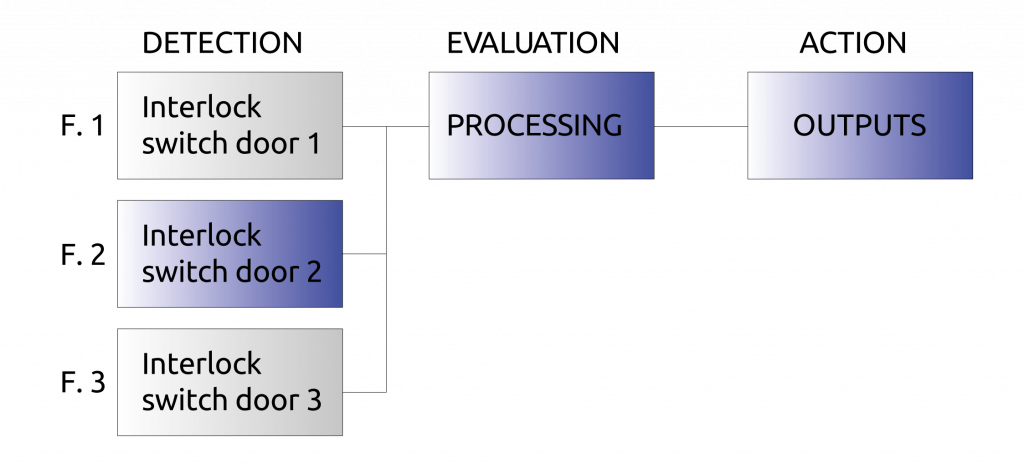
Structure of a safety function

A safety function is typically starting with a detection and evaluation of an ‘initiation event’ and ending with an output causing an action to a ‘machine actuator’

Realization of a Safety function

A safety function is usually made by a series combination of three sub-functions performing respectively the tasks of Detection, Evaluation and Action.

Each sub-function can be implemented by:

  • Using previously validated subsystems
  • Designing new subsystems
  • A combination of both alternatives above

Any of the technologies available (electric, hydraulic, pneumatic, mechanical) individually or in combination may be used.

The risk reduction provided by each safety function does not cover the overall risk of the machine, but only that part of the risk resulting from the application of that safety function. This measure helps to avoid an unduly increase of complexity in the execution of calculations because the reliability data of components of the safety-related control system that do not contribute to that safety function are not considered.

Example:

A hazardous movement is safeguarded by a fence fitted with five guards. The opening of any of the five guards stops the dangerous movement.

Four separate safety functions can be considered, one for each door, if it is assumed that only one door is opened at a time.

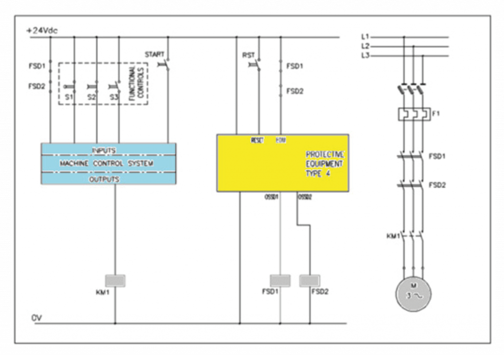
Per l’integrazione di un sistema di controllo relativo alla sicurezza nel sistema di controllo della macchina (MCS) devono essere applicati i seguenti principi:

  • Il sistema di controllo relativo alla sicurezza è separato e indipendente dall’MCS
  • Il sistema di controllo relativo alla sicurezza è destinato esclusivamente alla protezione diretta o indiretta delle
    persone; non partecipa attivamente al processo della macchina e si attiva solo al verificarsi di una situazione di pericolo
  • L’affidabilità dell’MCS non assume alcun ruolo per l’esecuzione della funzione di sicurezza. È l’affidabilità del sistema di controllo relativo alla sicurezza a destare preoccupazione; maggiore è la probabilità che una persona sia esposta al rischio, maggiore dovrebbe essere la disponibilità del sistema di controllo relativo alla sicurezza
  • Quando si verifica un guasto pericoloso nel sistema di controllo relativo alla sicurezza, la macchina viene portata in uno stato sicuro. Il riavvio del processo della macchina è accettato solo dopo la riparazione e il ripristino del sistema di controllo relativo alla sicurezza
  • È anche possibile che un sistema di controllo relativo alla sicurezza esegua funzioni di sicurezza e funzioni di comando della macchina (ad esempio una barriera fotoelettrica di sicurezza o un dispositivo di controllo a due mani possono essere utilizzati sia per la protezione che per il riavvio del ciclo).

Fig. 3 – Example of integration of a safety-related control system with a PLC

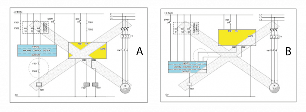
A – A failure to open (e.g. due to welded contacts) of KM1 prevents stopping of the motor.
B – If the outputs of the SRP/CS are connected TO the inputs of a standard (non-safety) PLC, hw and sw faults within the PLC or the failure of KM1 can prevent stopping of the motor.

Fig- 4 – Examples of an incorrect integration